
How to Calculate Moment of Inertia Matching for Servo Motors and Planetary Gearboxes?
A Complete Guide from Entry to Mastery
In the world of automated transmission, the term “Inertia Matching” is sometimes considered only after torque and speed. Some engineers only realize the severity of the problem when they encounter violent oscillations or severe positioning overshoot during the debugging phase. Looking back, they find that the inertia of the load reflected to the motor shaft was never seriously calculated during selection.
So, how exactly do you calculate the moment of inertia when matching a servo motor with a planetary gearbox? What is a reasonable range for the inertia ratio? This guide provides a detailed roadmap from basic concepts to complete engineering examples.
1. What Exactly is the Moment of Inertia? (Explaining it in one sentence)
The Moment of Inertia—referred to as J or I—refers to the inertia of an object to maintain its original state of rotational motion as it rotates around an axis. In rotational motion, it plays the same role as mass in linear motion: the larger the mass, the harder it is to push; the larger the inertia, the harder it is to accelerate or decelerate.
In the mechanical processing industry, there is a popular saying: “Flywheel inertia = rate of change of speed × flywheel distance / 375,” used to convert the moment of inertia into a form more convenient for engineering calculations. Regardless of the formula used, the core argument remains: large inertia increases the mechanical constant of the system, slows down the response, lowers the system’s natural frequency, and easily generates resonance. This limits the servo bandwidth and affects positioning accuracy and response speed.
Long-tail Keyword: Mechanism of the influence of moment of inertia on servo system response.
When a motor drives a load, the output torque T, total system inertia J, and angular acceleration \alpha satisfy the relationship T = J \times \alpha. The significance of this formula is that if the motor output torque is fixed, a larger total inertia results in a smaller angular acceleration—meaning the time from the controller issuing a command to the system completing execution is extended. Conversely, if the angular acceleration fluctuates, the system becomes unstable, severely affecting processing accuracy.
A fundamental principle in system design is: provided structural strength is not compromised, the smaller the inertia, the better the dynamic characteristics; the larger the inertia, the greater the load on the motor, making it harder to control.
2. Core Principles of Inertia Matching between Servo Motors and Planetary Gearboxes
2.1 How Planetary Gearboxes Change the Inertia Relationship
Without a gearbox, the servo motor rotor is rigidly connected to the load, and the load inertia J_L is the total inertia the motor shaft needs to drive. When a planetary gearbox is introduced, the situation changes fundamentally.
A planetary gearbox can “amplify” the motor’s sense of control by the square of the reduction ratio. If a planetary gearbox with a ratio of 1:10 is used, the load inertia reflected back to the motor side is reduced by the inverse square of the transmission ratio—meaning the reflected value J_{L\_reflected} = J_L / i^2.
In simple terms: the larger the reduction ratio, the smaller the load inertia the motor “feels,” which is a huge benefit for the servo system.
Long-tail Keyword: Principle of reflected inertia by the inverse square of the reduction ratio.
When the load’s moment of inertia is reduced to the motor shaft, it decreases by a factor of 1/i^2. Why the square instead of a linear ratio? Because the reduction ratio affects not only the speed (linear relationship) but also the square relationship of torque and acceleration transmission. This is the key role of the planetary gearbox: it doesn’t just change speed and torque; it “shrinks” the load inertia reflected to the motor side via the square of the ratio, allowing the motor to control the load more easily.
2.2 Total Inertia Calculation Formula
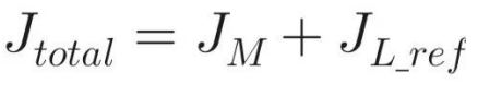
The total inertia of the feed axis J_{total} consists of two parts: the servo motor’s own rotor inertia J_M, plus the load inertia reflected to the motor shaft J_{L\_ref}. The formula is:
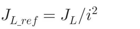
Where the reflected load inertia J_{L\_ref} is:
In precise engineering, the planetary gearbox’s own inertia should also be considered:
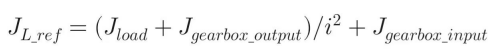
However, in standard practice, if the gearbox inertia is significantly smaller than the load inertia, it is often ignored for simplified selection.
3. Moment of Inertia Formulas for Common Load Shapes
To calculate the specific value of J_L, we use formulas based on mass distribution.
Long-tail Keywords: Solid cylinder load inertia calculation formula, Disk moment of inertia calculation method.
3.1 Solid Cylinder/Disk Rotating Around the Center Axis
Common in ball screws, gears, and rotary tables. For uniform mass distribution:
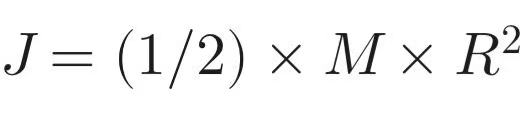
- M:
Mass (kg) - R: Radius (m)
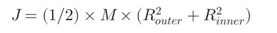
3.2 Hollow Cylinder Rotating Around the Center Axis
3.3 Rectangular Solid Rotating Around the Central Axis
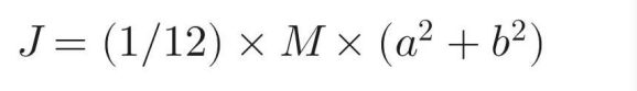
• a, b: Length and width of the cross-section.
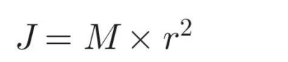
3.4 Point Mass in Circular Motion
When the load is concentrated at a point rotating around an axis:
3.5 Equivalent Inertia Conversion for Linear Motion
When converting linear motion to rotary motion via a ball screw:
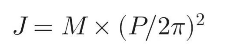
• M: Total mass of linear motion parts (kg)
• P: Lead of the screw (m)
Long-tail Keyword: Method for reflecting ball screw load inertia to the motor shaft.
4. The “Golden Ratio”: What is a Reasonable Inertia Ratio?
After calculation, you must evaluate the result using the inertia ratio K:
This is the ratio of reflected load inertia to the motor’s rotor inertia. The matching principle states that this ratio should not be too large, or the system will oscillate or lose control.
Recommended Inertia Ratio Ranges by Application:
• 1:1 is the theoretical ideal: The system can be tuned very tightly with optimal control. However, this is rarely necessary or cost-effective in practice.
• High Dynamic Response Scenarios (Semiconductor manufacturing, robotic arms, precision positioning): It is recommended to keep the inertia ratio below 3 to 5 times. This allows for sufficient bandwidth and phase margin.
• General Industrial Automation Scenarios (Conveyor lines, general machinery): An inertia ratio within 5 to 10 times is usually acceptable.
• CNC Machine Tools: For metal cutting machines, a stricter recommendation is an inertia ratio of less than 5 times.
• Extreme/Heavy Conditions (Mining machinery): Even if the ratio approaches 10, the system can remain basically stable with proper tuning.
Long-tail Keywords: Servo motor inertia ratio recommended values, High dynamic response inertia matching requirements.
5. Complete Engineering Calculation Example
Let’s integrate these theories into a single engineering instance.
Long-tail Keywords: Servo motor planetary gearbox selection example, Moment of inertia matching calculation case.
Background
An XY positioning platform with a Z-axis vertical lifting mechanism driven by a ball screw.
• Total mass M = 50 kg
• Ball screw lead P = 0.01 m (10mm)
• Screw dimensions: Length L = 0.6 m, Diameter D = 0.025 m
• Screw material density \rho = 7850 kg/m³
• Coupling inertia J_{coupling} \approx 5 \times 10^{-4} kg·m²
• Max velocity v_{max} = 0.3 m/s
• Acceleration time t_a = 0.2 s
• Planetary gearbox ratio i = 10
Step 1: Calculate Total Load Inertia (J_L) at the Screw Axis
• A. Linear Motion Equivalent Inertia: J_{linear} = 50 \times (0.01 / 2\pi)^2 \approx 0.01267 kg·m²
• B. Ball Screw Inertia:
• Mass M_{screw} = 7850 \times \pi \times 0.0125^2 \times 0.6 \approx 2.312 kg
• J_{screw} = (1/2) \times 2.312 \times 0.0125^2 \approx 0.000181 kg·m²
• C. Coupling Inertia: 0.0005 kg·m²
• Total J_L before reduction: 0.01267 + 0.000181 + 0.0005 \approx 0.01335 kg·m²
Step 2: Reflect J_L to the Motor Shaft via Gearbox
With ratio i = 10:

Step 3: Choose Servo Motor and Verify Ratio
Suppose we select a 200W servo motor with rotor inertia J_M = 0.27 \times 10^{-4} kg·m².
Inertia Ratio Check: K = 1.335 \times 10^{-4} / 0.27 \times 10^{-4} \approx 4.95
Since 4.95 is approximately 5, it falls within the recommended range for high-dynamic positioning.
6. Typical Consequences of Inertia Mismatch
6.1 Inertia Ratio Too Large (J_L \gg J_M)
• System Instability: Low stiffness, slow response, and high tendency for oscillation.
• Motor Overheating: The motor works excessively hard to pull a heavy load or control its momentum, shortening the lifespan of coils and bearings.
• Accuracy Loss: Tests show that in robotic arms, excessive end-effector inertia can reduce positioning accuracy by over 10%.
6.2 Inertia Ratio Too Small (J_L \ll J_M)
• High-Frequency Vibration: Because the load is too light, it responds too quickly to speed changes, while the motor rotor’s inertia acts with a slight lag, causing jitter.
Long-tail Keywords: Symptoms of servo motor inertia mismatch, oscillation, overshoot, overheating, inaccurate positioning.
7. Five Common Pitfalls in Selection
In extensive engineering practice, the following five points are the most frequent “traps” engineers fall into:
Pitfall 1: “Focusing only on motor power while ignoring inertia matching”
Looking only at whether torque and power are sufficient and skipping the inertia matching stage is the most common cause of servo system oscillation, overshoot, and even total loss of control. Many high-end precision devices fail during commissioning, with field engineers spending hours adjusting PID parameters to no avail, simply because inertia matching was neglected during the selection phase.
Pitfall 2: “Blindly pursuing a high reduction ratio”
Some believe that the larger the reduction ratio, the better, assuming it will minimize the equivalent load inertia on the motor side. However, if the reduction ratio is too high, the output speed will be severely limited by the motor’s rated speed. Furthermore, the torque required from the gearbox will increase significantly, necessitating a re-verification of the gearbox’s rated torque and overload capacity.
Pitfall 3: “Ignoring the planetary gearbox’s own moment of inertia”
In low-power systems or when using small gear ratios, the gearbox’s own inertia might seem negligible. However, in precision control scenarios with high gear ratios, the input shaft inertia of the gearbox must be accounted for. It is essential to confirm the input shaft inertia values provided by the manufacturer to ensure no part of the calculation chain is missing.
Pitfall 4: “Converting everything at once without a detailed breakdown”
Applying a total formula directly without breaking down the load components makes it easy to overlook specific parts. This makes it difficult to troubleshoot or trace errors if problems arise. It is highly recommended to list every load component individually, perform a complete summation, and then compare the total reflected inertia to the motor inertia J_M.
Pitfall 5: “Forgetting to set the inertia ratio parameter in the drive during commissioning”
Even if the mechanical design and assembly are perfect, the system performance will be hindered if the servo drive retains its factory-default inertia ratio. Most modern servo drives support automatic load inertia identification and real-time parameter adjustment. Enabling these manual or automatic calculation functions significantly enhances system response robustness and protection.
8. How Servo Drives Help Solve Inertia Matching Issues
After the mechanical selection and design are complete, proper tuning of the servo drive is the final critical step. Modern servo drives offer several methods to mitigate or resolve inertia mismatch issues:
Auto-Tuning/Identification Function: Many servo drives can automatically identify the load inertia and adjust control parameters in real-time to compensate for inertia variations. Running a “one-touch” auto-optimization can verify if the load inertia ratio is set correctly, optimizing the position loop, velocity loop, and other parameters.
Manual Parameter Adjustment: If auto-tuning is unavailable or if finer control is required, parameters such as velocity loop gain and position loop gain—which are directly related to inertia—can be adjusted manually. This requires professional experience to avoid system instability.
Filtering and Damping: For systems with high inertia ratios, filters (such as low-pass filters or notch filters) can be used to suppress mechanical resonance and improve system stability.
In summary, beyond mechanical inertia matching, the parameter settings of the drive are a decisive factor in system performance. The two are complementary.
9. Conclusion and Engineering Recommendations
The matching of the moment of inertia between a servo motor and a planetary gearbox is fundamentally a complete calculation workflow: starting from the load shape and the calculation of J_L, reflecting it to the motor side via J_L / i^2, incorporating the gearbox’s own inertia to find J_{L\_reflected}, and finally comparing it with the J_M from the motor manual to determine the inertia ratio K.
Key engineering recommendations include:
• Finalize the Inertia Ratio: For standard low-dynamic systems, the ratio should generally not exceed 10 times. For high-dynamic precision positioning, it should be kept within 3–5 times. If the ratio exceeds these limits, adjustments can be made by reselecting the gear ratio, using a high-inertia motor, or modifying the mechanical structure.
• Component-Based Calculation: When calculating J_L, calculate each part of the load separately before totaling them. Do not rely on “rough estimates.” A complete checklist ensures maximum reliability.
• Database Verification: Always check the technical data. J_M for the motor and the inertia of the gearbox are fixed values found in manufacturer catalogs. Clarifying these parameters is the only way to guarantee the accuracy of your inertia matching results.
Whether it is CNC machine tools, robot joints, printing equipment, or automated production lines, as long as a servo motor and planetary gearbox combination is used, calculating the moment of inertia and ensuring inertia matching is unavoidable. We hope this guide helps you avoid detours during selection and choose the most suitable configuration the first time.
Servo motor inertia matching, planetary gearbox inertia calculation, reflected inertia ratio K, servo system oscillation, PID tuning, reflected load inertia formula, high-dynamic response requirements.
